
Earlier this week I've finished the Sample&Hold, Internal Clock and Analog Switch part:

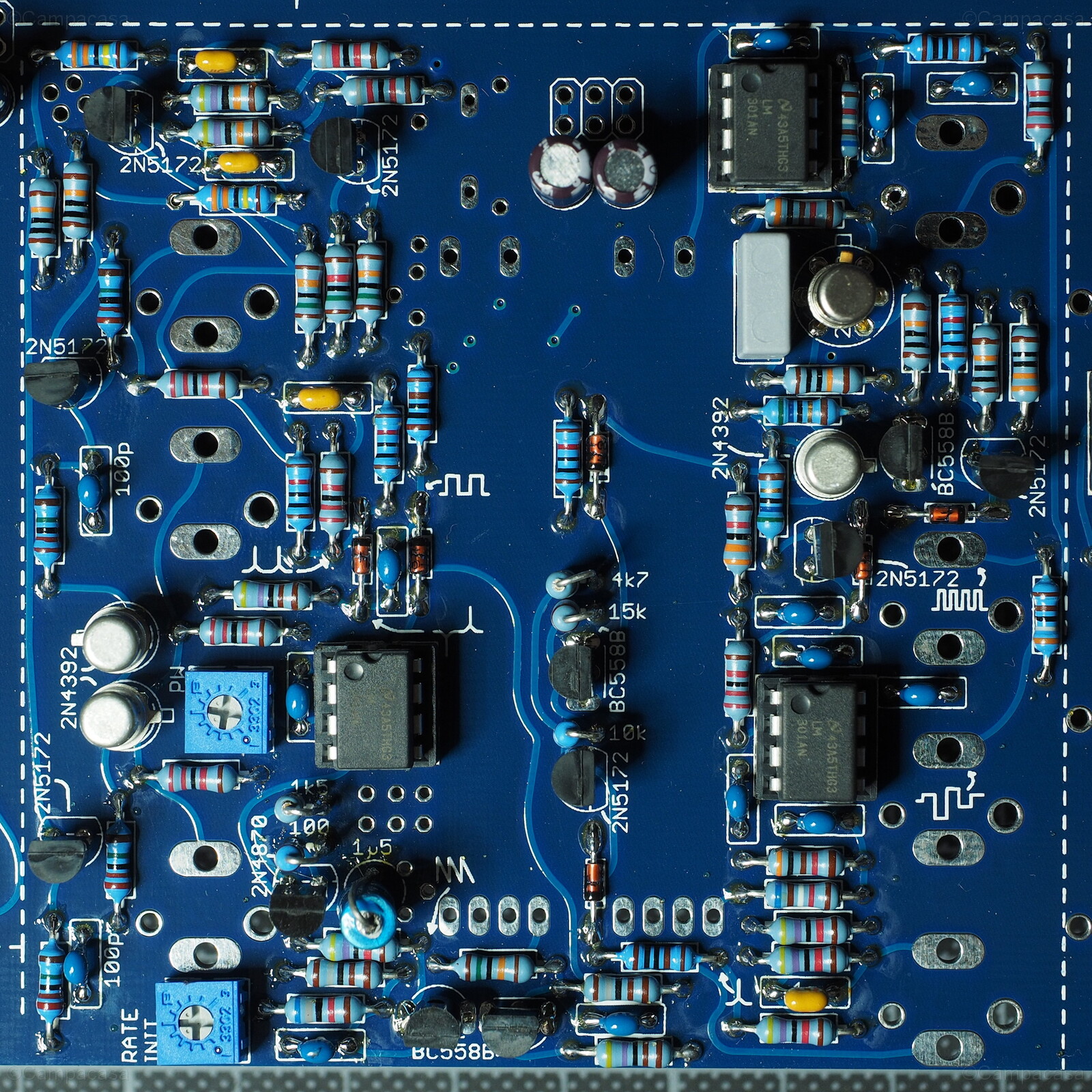
20150509_171032_5472c
Main Board, Sample&Hold, Internal Clock and Analog Switch Completed
Component side, jacks and sliders still missing.
The 1.5µF electrolytic capacitor (bright blue) at the bottom wasn't available with Mouser, but luckily I had a few of these from the past. Then I had made a little mistake: Soldered in a 10Ω resistor instead of a 100Ω one (near the 1.5µF capacitor, in vertical position). I only noticed when a 10Ω resistor was missing for the next section, the amplifiers part. Removing the vertically positioned resistor and putting back in the correct one was not that easy.
[Update] Then only later I detected that the analog switch was not working correctly. Channel A was always on. I had overlooked to solder one side of a 3.3MΩ resistor that controls one of the 2N5172 transistors, which actually can be clearly seen in the top-left corner of the above image. The fix was thus easy, luckily.
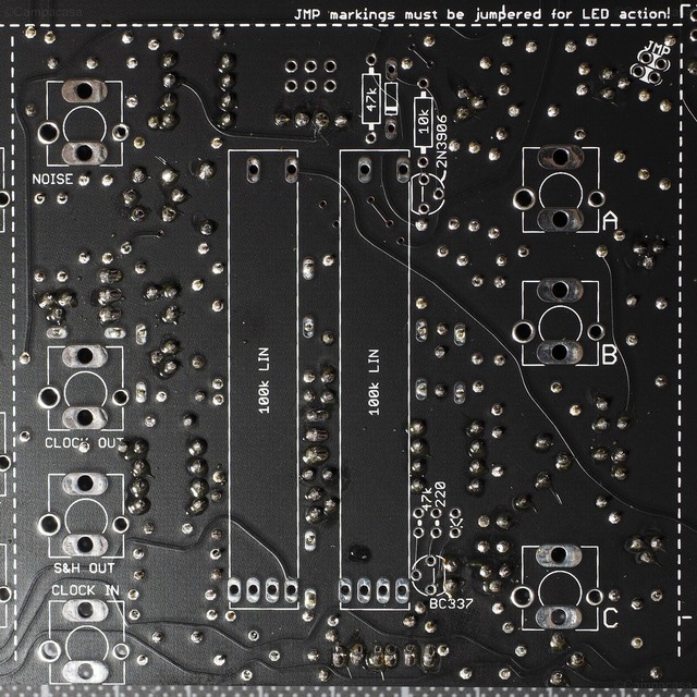
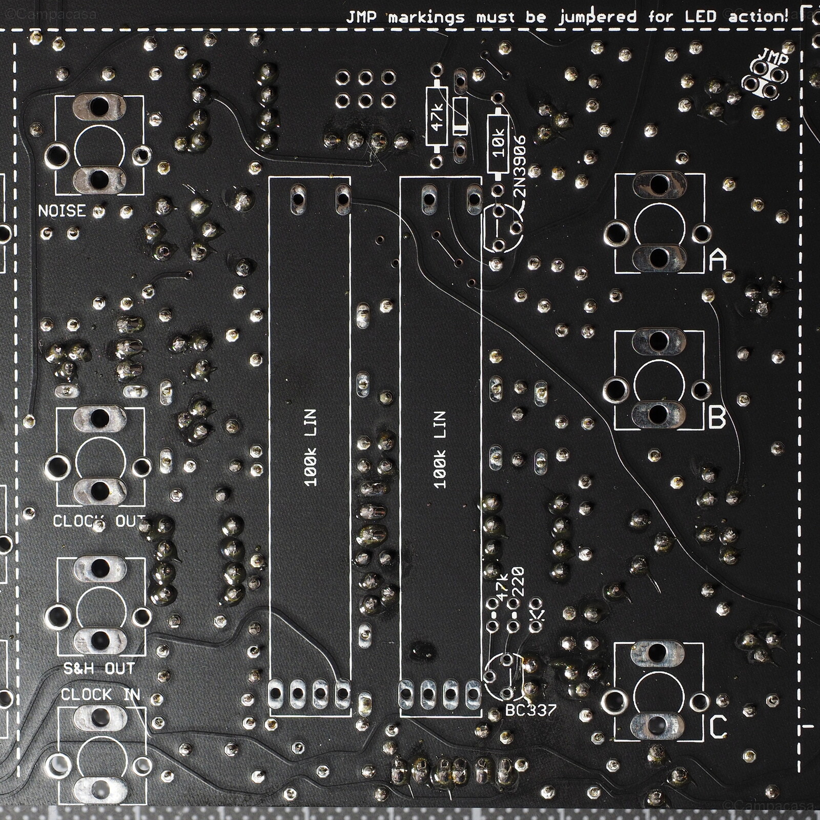
20150509_171254_5474c
Main Board, Sample&Hold, Internal Clock and Analog Switch Completed
Back side, jacks and sliders still missing.
And thus also the amplifiers part was finished:

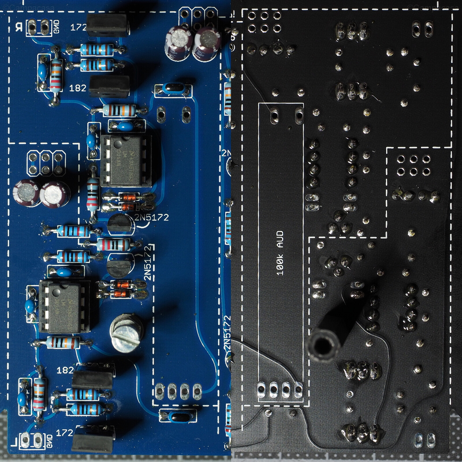
20150509_171157_5473m
Main Board, Amplifiers Completed
Connectors and slider still missing.